Arduino solar aimer
This is the first "more advanced" thing I did with an Arduino. Well, more advanced than just turning on and off some leds that is. I wanted to build something that would aim solar panels towards the sun, increasing their efficiency.
I did this in 3 iterations, each one extending the previous one.
- First a construction where I steer the servos by buttons myself
- Then a construction where the servos are steered by light resistors
- And finally a construction where I add a bigger frame so I can put solar panels on it.
Requirements§
- 2 Micro 9g servo motors (2x 1.2 USD)
- 4 Light dependent resistors (0.54 USD)
- 1 Cheap Arduino (nano) (1.64 USD)
- Some dupont wires (2.64 USD)
- 4 10k resistors (0.76 USD)
- 1 breadboard (1.99 USD)
- 4 pushbuttons (0.99 USD) (Only for the first iteration)
So you can build this for less than 10 USD. (Prices shown are at time of writing)
Iteration 1: Manual aiming§
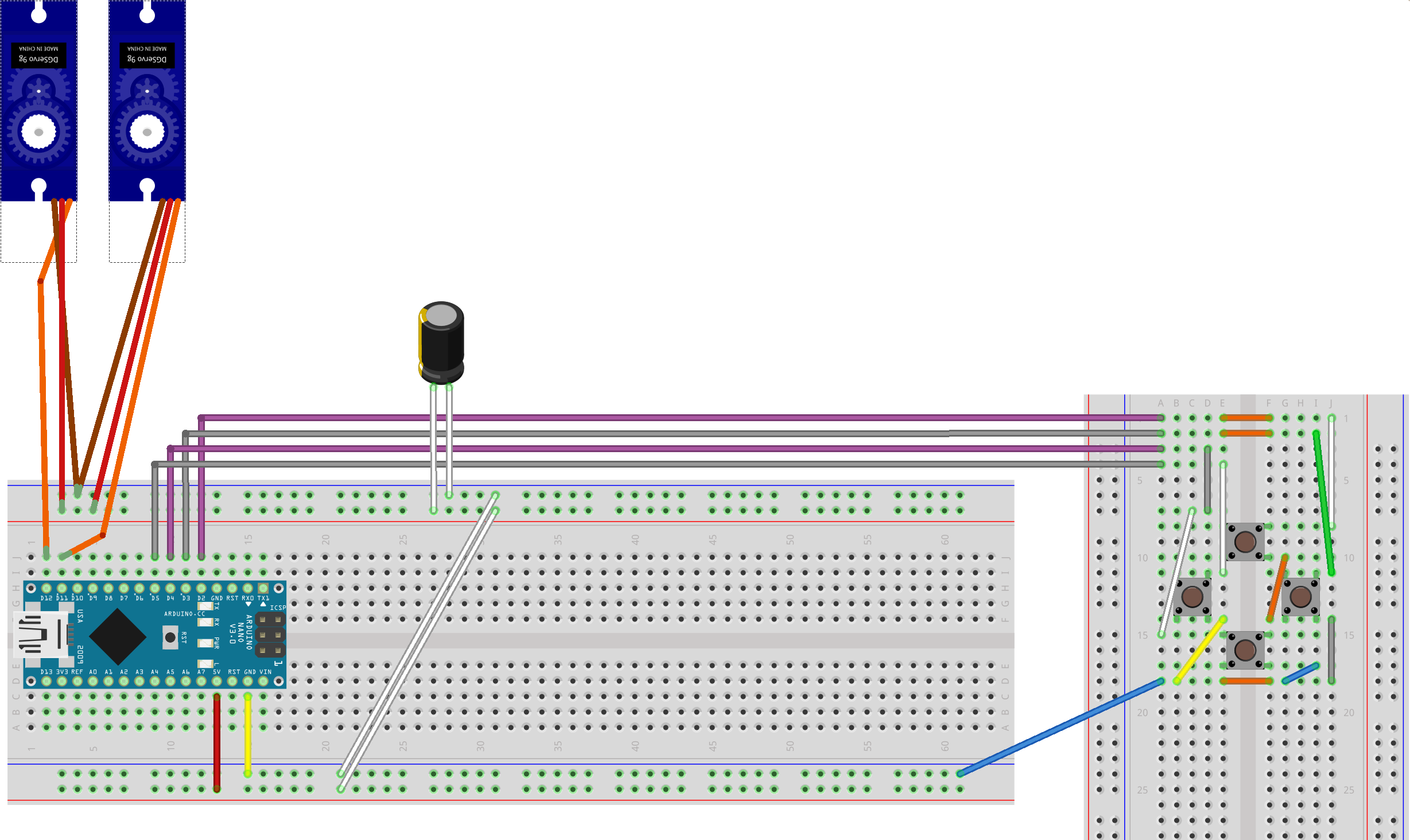
The first iteration is being able to steer the servos manually.
When I press the right button the pointer should move right, when I press the forward button it should move forward et cetera.
2 servos will be placed on top eachother. The bottom servo determines the movement on the horizontal plane and the top servo the vertical plane.
The top servo is attached to the bottom one by it's side.
A video of this in action§
A schematic of the breadboard:§
The code§
The code can be found on GitLab
This repo also includes a Fritzing file which includes the breadboard schematic.
If you change the MOVE_STEP variable to for example 5, the servo will move more per tick.
You'll then get something that moves like this.
Iteration 2: Replacing the buttons by Photoresistors§
Instead of me manually directing where the pointer should aim we'll add some automation by using photoresistors. (Light dependent resistors)
Most of this is based on this Instructables post.
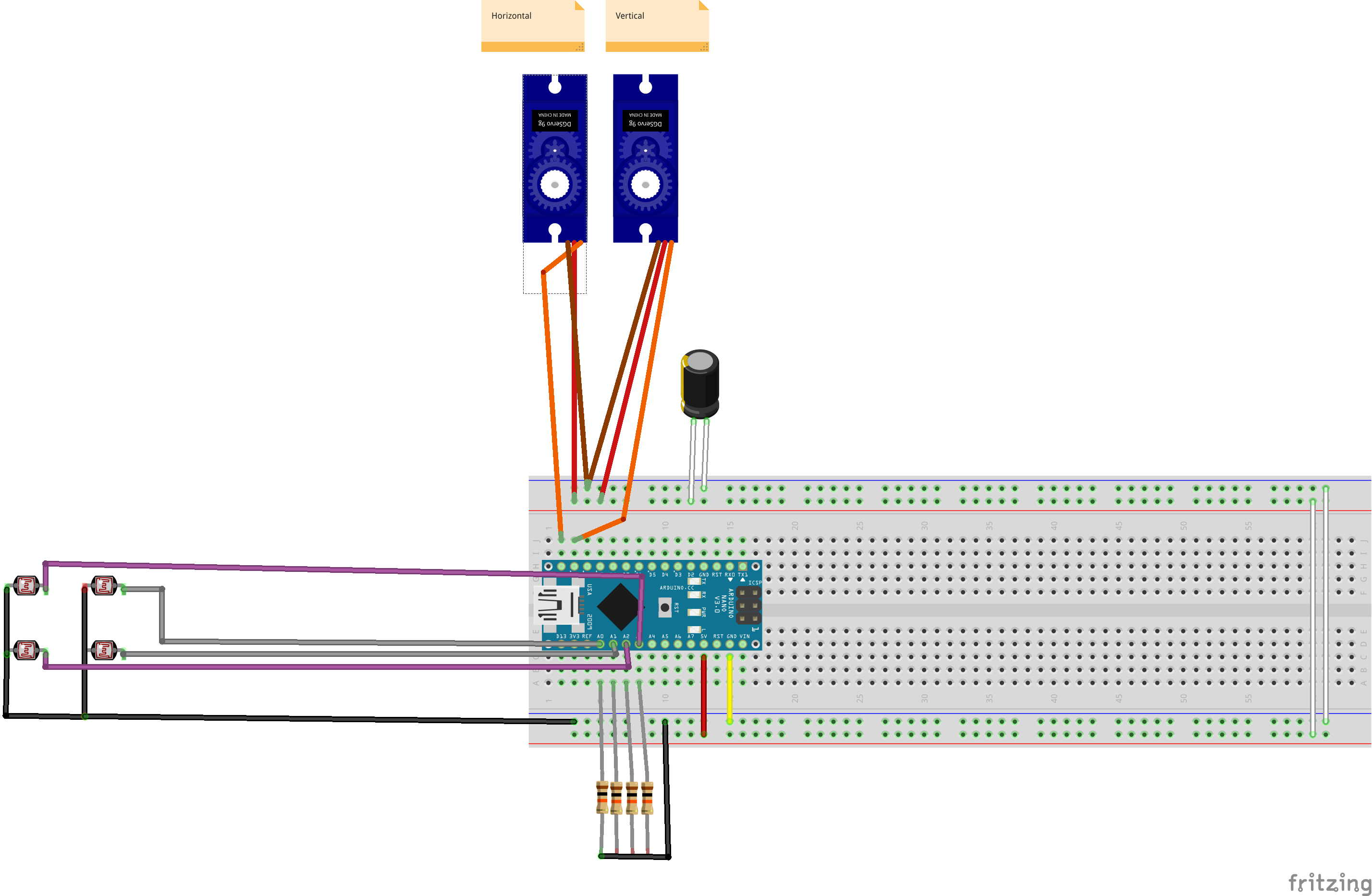
The main idea is that you have 4 sensors which are partitioned into 4 quadrants (Top Right, Bottom Right, Bottom Left, Top Left).
A division is made by 4 flat pieces of wood so that the resistor is not influenced by the light from the other resistors' partitions.
In the code you will then determine which direction receives more light and instruct the servos to point the "stick" to that direction.
Video of this in action§
A schematic of the breadboard:§
The code§
This can again be found on GitLab
And includes another Fritzing file with the breadboard schematics.
3rd Iteration: Building a frame for the solar panels§
Instead of taping the servos together I made something more permanent with wood and glue.
The wood sticks I also bought from AliExpress :D.
Video§
The code§
The only thing that changed is the construction. The actual aiming system is still the same.
We just want to point to where the most light is coming from, so the code is exactly the same as in Iteration 2.
Final Notes§
As you can maybe see in the last video the construction is quite wobbly.
That's because all the weight is being beared by the thin axes of the servos and the thin ice cream wood sticks aren't the ideal construction material.
I'd like to try making a construction where I make use of gears or a belt transmission so the weight can be beared by the surface below it.
But the next project will be actually mounting the solar panels I ordered on the construction and powering the arduino setup with them!
But I need to wait a while for that because it takes a while to receive the goods from AliExpress.

